High-performance bus bar shunt resistors are helping electric vehicle (EV) designers meet the challenges of the market in new ways. This article reviews the basics of shunt-resistor technology and outlines several recent improvements, including a new metal-injection-molding process and a new form factor. These innovations are leading to breakthroughs in minimizing power loss, reducing physical footprints and managing thermal and conductivity properties.
Overview of shunt resistor technology
A battery in an EV must supply 100 kW of power or greater in response to driver demand. A typical EV battery system consists of hundreds of lithium-Ion battery cells connected in series to generate a voltage of 350 V or more. The voltage, current and temperature of the battery system must be carefully monitored to control charging and discharging, to balance the charge between cells, to keep the cells within their safe operating area (SOA), and to calculate key battery parameters such as state of charge (SOC) and state of health (SOH).
The current sensor must be able to accurately measure currents from milliamps to hundreds of amps over automotive operating temperatures of -40° C to 125° C and an operating life of up to 20 years. A shunt-based current sensing design determines the current (I) by measuring the voltage (V) generated as I flows through a shunt resistor (R) placed in the battery line, as expressed by Ohm’s law:
V = I x R
Figure 1: Shunt current measurement. Source: Isabellenhütte

Figure 1 shows a typical EV arrangement where the shunt is placed in the battery return path. The shunt resistor is typically part of a module that also includes a battery management integrated circuit to measure the voltage across the shunt and communicates with the vehicle network over the industry-standard CAN bus. Note that the current flow can be positive or negative.
Design challenges with existing shunt technology
A practical implementation of a shunt-resistor measurement system poses several challenges for the designer.
The resistance of an “ideal” shunt resistor does not change with time, current or operating temperature; this is not true for a real-world device. For example, any resistor dissipates power according to the equation P = I2R. As I increases, so too does the temperature. In a real component, a change in temperature causes a change in the value of R, characterized in a resistor data sheet as the temperature coefficient of resistance (TCR). Additionally, component aging causes the resistance to change over time, and a real-world device also exhibits parasitic inductance and capacitance. At low currents, error may occur due to thermal electromotive force (EMF) — a voltage in the microvolt (μV) range caused by temperature variations across the shunt resistor.
Isabellenhütte has developed a range of specialized alloys such as Manganin, Isaohm and Zeranin for current measurement applications. Shunt resistors made from these alloys combine low resistances with extremely low inductance, TCR and thermal EMF, and excellent long-term stability.
As shown in Figure 2, the shunt resistor is then combined with two copper (Cu) terminals using Isabellenhütte’s proprietary ISA-WELD® electron-beam welding process. This approach integrates the alloy into a bus bar with a combination of Cu-Manganin®-Cu, or the Manganin can be substituted for another resistive alloy.
Figure 2: The ISA-WELD® process results in a highly stable shunt resistor assembly. Source: Isabellenhütte

The resistance of the shunt resistor is a function of the resistivity (ρ) of the alloy, the length of the resistor, and its cross-sectional area. Manganin® has a resistivity of 43 µΩcm; pure copper, by comparison, has a ρ value of 1.7 µΩcm.
Advantages and disadvantages
Once the shunt assembly is formed, the voltage across the shunt resistor must be sensed and measured with minimum error.
Figure 3: Three options for connecting the measuring circuitry to the shunt resistor assembly. Source: Isabellenhütte

The designer has a choice of several sensing connections; Figure 3 shows some common approaches. The table below summarizes key characteristics of each method.

Contact Isabellenhütte for more information on these connection methods and their suitability for a specific application.
MIM technology increases current measurement precision
Figure 4: A prototype MIM shunt resistor with integrated sense pins. Source: Isabellenhütte
Isabellenhütte is developing the next-generation of sensing technology with the innovative metal-injection-molding (MIM) process. MIM allows the fabrication of metallic components with complex geometries. It has its origin in plastic injection molding technology. Metals can be processed using conventional methods of casting and machining much more heavily than plastics.
MIM combines the simplicity of injection molding with the material properties of metal; metal powder is mixed with an organic binder to form a feedstock that is shaped on an injection molding machine. The binder is then removed and the component is sintered in a furnace at a high temperature, giving a metallic product that combines the mechanical advantages of sintered components with the diversity of injection molding. In this way, components with sophisticated geometries can be made in a single piece, which can only be produced in several stages in conventional processes. MIM-based technology is available now.

Figure 4 shows a MIM shunt resistor with integrated sense pins. Both the resistance element and the sense pins are made of the same material. This enables direct voltage tapping at the shunt resistor, which improves the measurement result and the long-term stability. The measurement does not generate thermoelectric EMF and the absence of copper in the current path leads to very small values of TCR.
The BAX product line allows precision measurement of higher currents
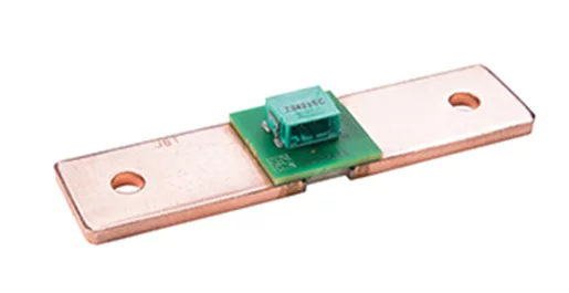
As the maximum current available from an EV battery continues to rise, precision measurement demands shunt resistors with lower resistances. In response, Isabellenhütte has introduced the BAX shunt (Figure 5) that features a larger form factor than earlier devices such as the BAS family. The BAX is the same length (84 mm) as the BAS series but features a width of 36 mm and a thickness of 4 mm compared to the BAS dimensions of 20 mm and 3 mm, respectively. The BAX Manganin element is shorter with a larger cross-section than the BAS element, allowing for a lower shunt resistance; the initial product offering includes two variants with resistances of 20 µΩ and 5 µΩ.

Figure 5: The BAX form factor gives improved performance in higher current applications compared to standard devices. Source: Isabellenhütte
Conclusion
Current sensing is a key component in electronic battery management systems for hybrid and electric vehicles, and also finds applications in gas-powered vehicles, power generation and welding equipment.
Improving the performance of the current measurement system requires improvements across multiple fronts, including the shunt resistor and the sensing system. Isabellenhütte has recently introduced a new manufacturing technology (MIM) and a new product family; together they enable higher performance for both current and emerging applications.
For more information about this products, please contact Nijkerk Electronics.