Smartphones change people’s habits and make people enjoy the convenience of touch solutions. Winstar‘s vision is to devote itself to the human-machine interaction interface and communication technology innovation.
Touch panels can be divided into resistive touch panels (RTP) and capacitive touch panels (CTP) based on electrical principles. There are two types of capacitive touch: surface capacitive touch (SCTP) and the other is projected capacitive touch (PCTP), also called inductive capacitance.
Difference between RTP with CTP touch

RTP

CTP
SCTP (Surface Capacitive Touch Panel)
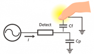
There is a uniform, transparent conductive layer (ITO) on one side of the SCTP and an electrode connecting to the controller on the four corners. The SCTP controller IC provides charging to make the ITO layer generate a uniform electric field. When a finger touches the panel, four-side of electrodes will create a current flowing to the contacts. The current intensity is proportional to the distance between the finger and the electrode. In the meantime, the IC detects the current value and calculates the XY coordinates of the contact point accordingly.
Disadvantages of SCTP:
- The light transmittance is uneven, the color is easily distorted, and the image of characters may be blurred.
- Pincushion touch signal will be distorted.
- Malfunction occurs when a large area of palms or hand-held conductive objects gets close and worsens in humid weather.
- No signal responded when wearing gloves or holding non-conductive objects.
- When the ambient temperature, humidity, or electric field changes, it gets inaccurate signal drift easily.
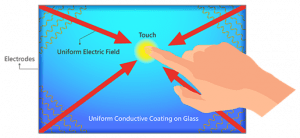
Schematic of SCTP principle and structure
PCTP (Projected Capacitive Touch Panel)
Projected capacitive touch (PCTP) is divided into self-capacitance and mutual-capacitance.
Self-capacitance (PCTP) is a crossed (ITO) electrode array on the glass’s surface. One side of the electrode is grounded, and the other side is connected to the driving circuit to form a capacitor loop. When a finger touches a self-capacitance panel, it will increase the panel capacitance. The touch IC will scan and detect the crossed electrode arrays’ capacitance and determine the X-axis and Y-axis coordinates according to the Status change in capacitance before and after the touch.
The advantage is that the scanning speed is fast and only needs to scan the electrode number of X-axis and Y-axis in one cycle.
However, there are some disadvantages:
- Self-capacitance (PCTP) needs calibration when used for the first time or when the environment changes significantly.
- Multi-touch cannot be achieved if there’s a “ghosting” effect.
- It is easy to cause signal “drift,” which is affected by temperature, humidity, finger wetness, body weight, the dryness of the ground, and the interference from large external objects.
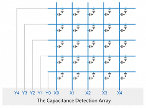
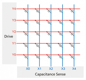
Crossed (ITO) electrode array is made on the glass surface. Mutual capacitance is the same as self-capacitance. The difference is that mutual capacitance is formed where two sets of electrodes intersect, and the two sets of electrodes respectively constitute the two poles of the capacitance.
When the touch IC scans, the horizontal electrodes send signals in sequence, and all the vertical electrodes receive the signals simultaneously. Then the capacitance value is obtained from the intersection of all the horizontal and vertical electrodes, which is equal to the second-dimensional distribution of the capacitance on the entire touch panel.
Therefore, the coupling between the two electrodes near the touchpoint will change when the finger touches the mutual capacitance panel resulting in decrease mend of the capacitance in the area. The touch IC will calculate each touch coordinate according to the data change of capacitance from the second dimension on the touch panel.
Therefore, mutual capacitance can accurately calculate each touch point’s coordinates even if multiple touchpoints exist. The advantages are no calibration needed, no “ghost point” effect, no “drift” phenomenon, and the actual multi-touch function is realized.
Schematic of PCTP principle and structure:
Self-capacitive
Mutual capacitive


In 2019, the COVID-19 pandemic spread out globally. Large-scale of infections lead to illness and deaths; Viruses mutate nowadays. More and more ferocious and highly infectious virus strains have been discovered continuously, such as Alpha, Beta, Gamma, Delta, Omicron, etc. In addition, to develop new vaccines and drugs actively, the isolation of infection channels is also an important measure. The vision of Winstar is to dedicate itself to the innovation of human-machine interaction interfaces and actively develop technologies and products to satisfy the market and customer’s needs.
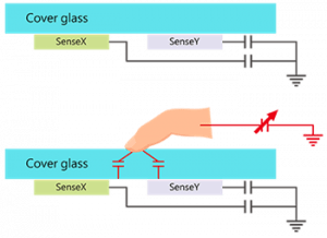
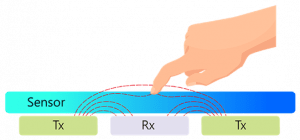
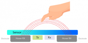
Hover Touch is a whole new Innovation of touch technology combining both mutual capacitance and self-capacitance to reach the floating touch. When the user’s fingers are far from the panel, signals are too weak to be detected, and the mutual capacitance signal has not been changed. However, the self-capacitance signals have increased gradually while the fingers are approaching. It can detect the coordinates of the fingers at a certain distance, and then the floating touch function will be fulfilled. When the fingers touch the panel, the mutual capacitance is detected for the electric field change, and the multi-touch function is also fulfilled.
Schematic of Hover Touch:
2D Touch Principle
3D Touch Principle
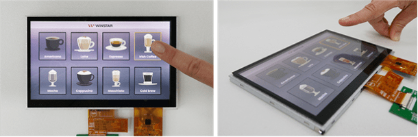
There are so many advantages of developing multi-touch and hover touch. Take Winstar model WF70A8 as an example (see first picture):
- It can be a three-in-one product structure bundled with CG (Cover Glass), touch panel, and display module.
- CG can apply the surface treatment with AG/AR/AF/AS without affecting the touch effect.
- Highly noise-resistant ability.
- It equips with non-touch single-point and multi-touch functions to support up to 5 touchpoints.
- It can send 38 channels of signal and receive 22 channels of signal and detect up to 836 nodes.
- It can be controlled accurately on the panel with the passive stylus (with 1mm of diameter). However, it depends on configuration, stacking, and sensing design.
- It supports Min 10mm / Max 30mm of the floating height with Single-point operation, and the panel can still be controlled.
- When your hands are stained with water or grease, you can operate the panel normally without worrying about soiling the panel.
- Wearing non-conductive cloth or gloves, the thickness of multi-point operation can support up to 2mm, and up to 5mm with the single-point operation. The panel can still be controlled normally.
- Supports Windows and Android operating systems.
- The speed is greater than 60Hz (in the condition of 10 points of touch).
If you want more information or if you have any questions, please contact Nijkerk Electronics!