The concept of control methods for cross-platform
I. Preface:
Smart Display has been widely used in various fields such as medical, industrial control, and automotive after products launched. Simply put, it is a display combined with a microcontroller, which can handle complex graphics loading, setting, display, and even input, and the outside device (host i.e.) can perform interactive operations with simple commands, so it is very suitable for various needs. Various types of applications displayed or controlled.
Smart Display supports a variety of communication interfaces. Currently the most commonly used ones are CAN/CANopen, RS485/Modbus, and more choices will be provided in the future. Among them, RS485/Modbus is a popular communication interface in the industry, and various RS485 devices at reasonable prices are easily available on the market. The line structure is simple, as long as two wires (RS485_A/RS485_B) can communicate, and the communication interface is usually presented in the form of “Serial Port” on an operating system, and each platform has a corresponding development function library. In addition, the Modbus protocol is quite easy to understand, so we put it as an example as following for experiments and explanations.
This article will introduce how to control Smart Display from simple to deep, understand its control principle, and finally introduce how to make cross-platform applications. Whether you are an industrial equipment expert or a DIY player, welcome to the world of Smart Display with us!
II. Requirements:
Smart Display_RS485
A Smart Display that supports RS485 interface is required for connecting test.
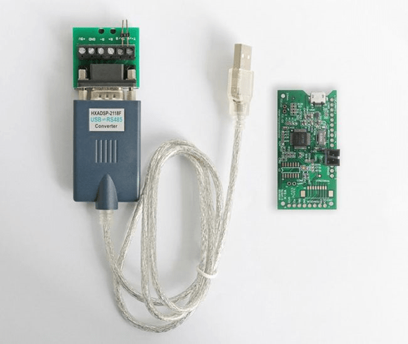
RS485 Dongle
Since a host like PC/Raspberry Pi normally does not have RS485 port, we can utilize various USB to RS485 dongle if necessary.
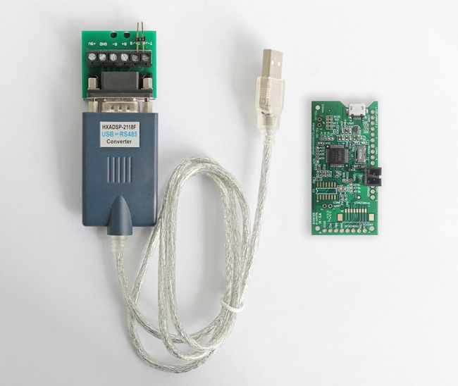
HOST Device
When reach the above requirements, then can choose a test bench execution environment as a Host. The only condition for a host device is to be able to read and write the series port of host no matter the OS is Windows, MacOS, various Linux (including Raspbian for Raspberry Pi), or the platform is Single Board Computer, Arduino etc.
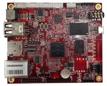
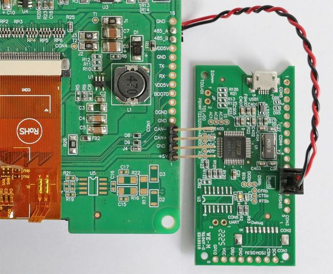
We create a single-board computers have built-in RS485 of Demo.set for convenience, which can be used as a host device as below picture directly.
III. Simple test for control interface:
Get the control code
In order to understand how to collaborate in Smart with a host. First issue we need to get the control code. The easiest way is to get it from Smart Display GUI Builder. GUI Builder is an excellent support software for Smart Display. It can help us learn, operate, design, and display user interface without hardware physical device, design UI without writing any program at all. With the WYSIWYG feature, user interface design can be done by dragging or clicking buttons or objects. In addition, there is a built-in simulator that shares source code with Smart Display, thus ensuring the same appearance and behavior as the physical device. Even better, it’s free!
► Contact for Smart Display GUI Builder
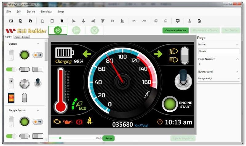
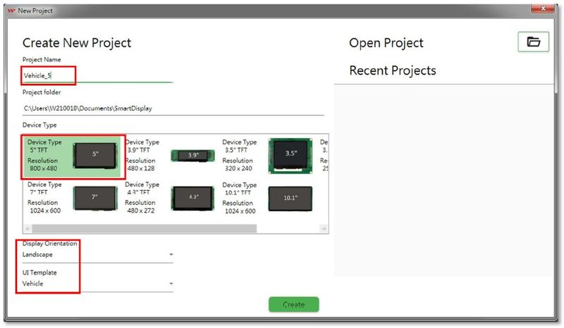
Double click GUI Builder to run the app in Windows OS, open a project. Here we choose the 5″ RS485 Smart Display WL0F00050000FGDAASA00, and the default scenario below is Vehicle. Input the project name, press Create button to create project. If it has been created before, you can also select project directly from the menu on the right.
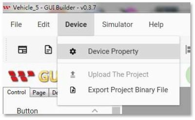
When the project is opened, select the interface first
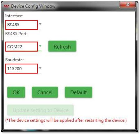
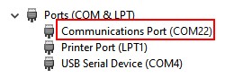
Select RS485 for the Interface, and the RS485 Port of host should be set as the actual port of the connected port for RS485 dongle. If there is any doubt, you can check the port name in the device administrator (repeatedly unplug it and see that it disappears or shows which one is displayed). Baudrate can keep the default value of 115200.
However, if there is no Smart Display RS485 device yet, it does not matter, as long as the Interface selects RS485, the RS485 Port can be ignored for now, because now we will just utilize the simulator, and will not connect to the Smart display device practically.
Click Simulator/Simulator with GUI to run:
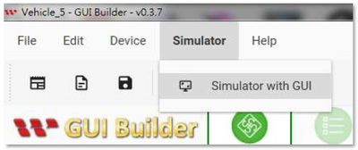
After execution, you can see the simulation screen, the control items of each object; and the communication data record on the right side of the screen. Change the value of any object to see the content of the command accordingly:
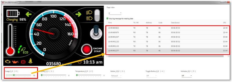
Every action will see two commands TX/RX, because the display device (even if it is actually an emulator now) will send back the same command as acknowledge after receiving the command to indicate that it has been received.
We record several different values for different objects, and the next step can be used to control the physical device.
Wire connection:
RS485 uses the differential pair to transmit & receive signals, so as long as these two wires can be connected, even the ground wire is not needed. The name of the signal line of RS485 is A/B, just follow it (A connect A, B connect B).
How is a host to transmit control codes from itself? As long as it can write to a serial port. However, there are two things to keep in mind before go ahead for testing.
1. Since the names of the Com Ports on different operating systems are different, please check and confirm before testing. For examples the following table:
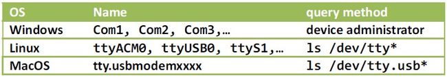
2. The permission of the Com Port of some operating systems is not open by default. It must be set before using it. Taking Linux/Ubuntu as an example, if the name of the Com Port is ttyUSB0, just execute it in the terminal:
sudo chmod 666 /dev/ttyUSB0
Below two test methods are provided:
Serial Port Terminal Control
Use the serial port terminal software that supports hexadecimal input, and directly input the hexadecimal control code after connecting:
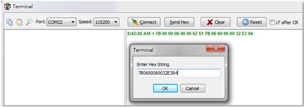
If it is normal, you should be able to see that the objects on the device act according to different control codes.
But this method is only used to test whether the connection is successful, and it is not very convenient in practical application. To achieve the best results, it has to be done through the program. As for which language? In fact, we can, let’s try it first with the popular cross-platform programming language python.
Use python
The following programs are executed using python3. The program structure is quite simple, just directly write three sets of control codes into the serial port every one second, so that the instrument on the device continues to rotate.
|
import serial “”” v000 = bytes.fromhex(‘7B06000600006251’) ser = serial.Serial(COM_PORT, 115200) |
The python source code can be executed on a variety of platforms, so as long as the serial port is named correctly, it should work fine with the appropriate connection test bench.
However, these fixed control codes as example must not be in line with practical applications, so we need to understand the content of these instructions in order to give full play to them.
IV. control code analysis
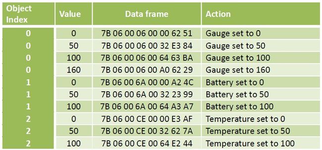
Comparative analysis
Compare commands with different values for the same object:
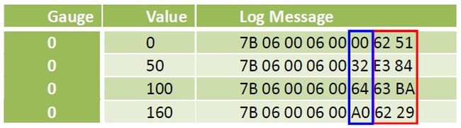
It is not difficult to find that the blue part is the value of the object we set.
Compare different objects, the same value command:
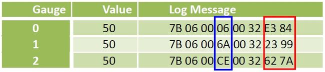
The blue part obviously refers to some kind of index or address to the object.
As for the data of the last two bytes, it seems that there are no rules. What are those messages meaning though? Let’s explain in following.
Control code analysis
In fact, the content of these 8 bytes is the so-called Modbus message. Simply use a picture to illustrate the meaning of each field:
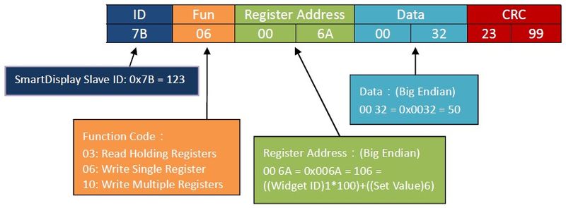
ID
Each Modbus device must have an identification code. Smart Display’s identification code is 0x7B = 123
Fun(Function Code)
Function code, indicating the purpose of this message, for example, 06 here is Write Single Register, which also writes a value to the specified place.
Register Address
The register address, which is the destination to be written to (that is, the address of the object).
Data
What to write (that is, the value of the object)
CRC
The result of CRC (Cyclic Redundancy Check) on the first 6 bytes is used to check whether there is an error in the data during the transmission process.
Do you have some concepts? If you want to know more, you have to look at what Modbus is.
V. Modbus Introduction
Modbus Protocol
The Modbus protocol is actually a data format. It basically defines the communication content of a master-slave architecture. Since it is only the definition of the data structure, it can communicate through various physical interface, such as RS232, RS422, RS485, and even the network.
Since there are already many teaching and explanatory documents on the Internet, Modbus will not be described in detail here. In fact, as long as you know some concepts, you can use Modbus freely.
Conceptual model
Modbus regards data transmission as “Register” access. Each device must define its own register type and address for external reference. The so-called transmission of data to the device is to write to the specified register, and to read the data is to read the specified register, which is simple and clear. In addition, the value stored in each address register is 16-bits.
Function code
According to the characteristics of the data, Modbus defines several methods of reading and writing, which are specified by the function code in the message.
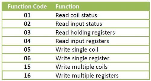
For Smart Display control programs, the most commonly used are 06: Write single register (write a 16-bits value) and Read holding registers (read the value of multiple registers).
CRC
The last 2 bytes seems the most mysterious part is actually not difficult. It’s just a CRC (Cyclic Redundancy Check) to insure the communication data. We don’t necessarily have to study its principle in depth (but in fact, it is just a table lookup and bit operation, and finally a 16-bit check code is obtained), as long as we understand how to use it.
VI. Control Smart Display objects
As mentioned earlier, each Modbus needs to define the type and address of the register, and now we will discuss this topic.
Register classification
Smart Display registers can be roughly divided into three categories:
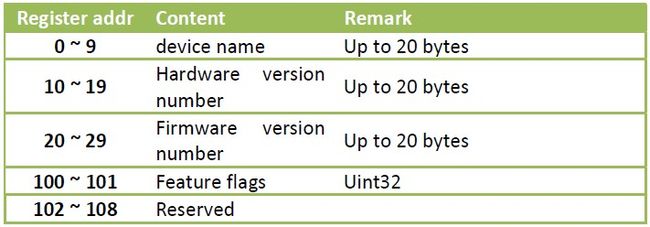
Device information (e.g. version, device name, etc.)
Use 04: Read Input Registers to read. These data will only be changed when the firmware is updated, usually when it is just connected, to obtain the device characteristic parameters.
Object properties (eg kind, location, etc.)
Use 03: Read Holding Registers/16: Write Multiple Register to read and write. These data affect the appearance of objects and usually do not change outside the design stage. To change the content, the Smart Display must be temporarily turned off before it can be updated.
Object Values (values that the object represents, such as RPM, on or off, percentage, etc., varies from object to object)
This is the main change item in the operation. Each element uses a 16-bit value, so it is set with 06: Write Single Register.
The following is an organized list of these registers:
Input Registers
Holding Registers
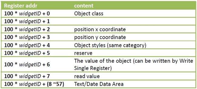
Early Smart Display supports only 10 objects, so the widgetID range is 0 ~ 9 (inclusive). The new version of the firmware has been expanded to 64, but the addressing method has been changed, which will not be discussed here.
With these data (although not complete, but enough for now), we can package the control instructions and send them to Smart Display for control. As for how to pack and how to add CRC code, it will be explained in the following chapters.
VII. User Interface
In order to put Smart Display into practical application, a suitable human-machine interface (especially Graphics User Interface, GUI) is still needed to maximize its effectiveness. At present, there are many choices for the cross-platform GUI development platform, and we use Qt to implement it here.
Many people think that Qt is just a GUI library, but in fact it is a fairly complete development framework. If the application is implemented entirely through its class library, the project can be easily ported to other platforms (PC/Windows, Mac/MacOS, Raspberry Pi/Raspbian, Android, iOS, Embedded, etc.) with little modification. The program is a development tool software that is worth investing in learning.
The newer version of Qt actually already supports the Modbus class library. But here for illustration, and to facilitate everyone to rewrite into other languages, we still implement this test program from the most basic serial port reading and writing.
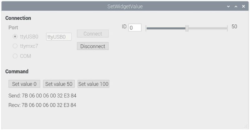
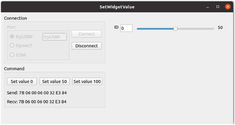
In addition to providing he function of selecting the serial port and transmitting the control code used in the previous example, this example further provides a horizontal lever in users interface of app window, which can set the value of the specified object. If you choose COM for the serial port, remember to fill in the actual number.
The following picture shows the execution screen of this program on Raspberry Pi and Ubuntu. The program does not need to be modified at all.
CRC operation
The CRC operation is actually not complicated. It is probably like below codes with Qt:
|
QByteArray SetWidgetValue::calculateCRC(QByteArray data) |
The contents of crcTable[] are:
|
const uint16_t crcTable[] = |
Not every codes are listed here. There is complete information in github that users can do download by themselves if interesting on programming, in this article we just know how to operate with the data format.
Data packaging
The following is the key function that calculates the control code according to the UI and sends it to Smart Display:
|
void SetWidgetValue::on_sbValue_valueChanged(int value) void SetWidgetValue::sendWidgetValue(int id, int value) |
If you are already familiar with Qt, the above code should not be difficult to understand. If you are not familiar with it, take a moment to study it, some of its concepts are actually quite good and worth studying in depth. After getting familiar with it, it is a good choice for developing cross-platform applications or quickly prototyping a system.
VIII. Advanced example
The previous example is only for a setting of the object value. There is a more complete example SmartDisplayConsole application program for interested readers to learn more about. The following picture is the execution screen on the Raspberry Pi:
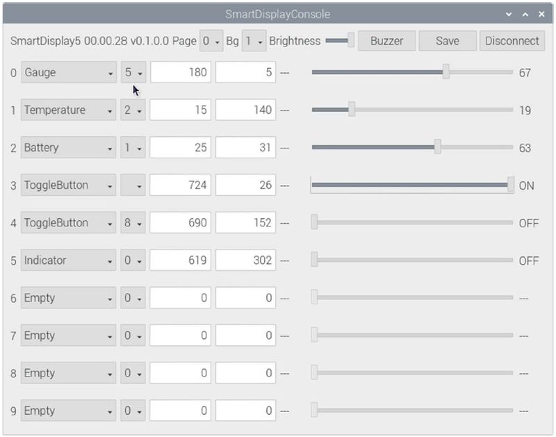
There is a github URL at the end of the article, and everyone is welcome to refer to and study together.
IX. Conclusion
We have explained every step of controlling the Smart Display, and also provide a variety of control methods. Using this knowledge and rich imagination, I believe that various sparks can be stirred up and more diverse products can be produced. Let’s create a better future with Smart Display together!
X. References
Serial Terminal Basics
https://learn.sparkfun.com/tutorials/terminal-basics/command-line-windows-mac-linux
Modbus
https://www.modbustools.com/modbus.html
https://www.modbusdriver.com/doc/mbusmaster.net/modbus.htm
XI. Sample source code
GettingStartedWithSmartDisplay
https://github.com/Smart-Display-Series/GettingStartedWithSmartDisplay.git
SmartDisplayConsole
https://github.com/Smart-Display-Series/SmartDisplayConsole.git
If you want more information or if you have any questions, please contact Nijkerk Electronics!