What you’ll learn:
- What are the key factors in optimizing mean time between failure (MTBF)?
- Developing the best strategy for MTBF.
- What to look for in MTBF test studies.
For designers of engineered electronics powering our most critical applications and devices, reliability is a common goal. At the same time, a design engineer or purchasing manager must have the ability to quantify reliability of the parts selected—a delicate balance between performance and dependability—to optimize total cost of ownership. On this landscape, a greater understanding of mean time between failure (MTBF) considerations can improve both reliability and costs.
Purchasing professionals at such organizations are all too familiar with budgets and the steps required for correlated selection and sourcing. Still, they may have limited insight into how to evaluate reliability reports, how to ensure statistically similar comparison among sources and options, and how these factors may affect their product design and development. Will a commercial-off-the-shelf (COTS) part suffice, or is S-Level (space-rated) required? Are all parts designated for a particular level the same amongst suppliers? And is MTBF data inherently reported in similar fashion from study to study and vendor to vendor?
These and other concerns represent deeper intelligence about how MTBF impacts product design, performance, and longevity. By clarifying how reliability data is obtained, measured, calculated, and interpreted, purchasing pros can evaluate options more consistently and successfully.
Defining Key Considerations in MTBF
The universal cross-industry reliability term, often expressed as MTBF, represents a projected number of operating hours before the first failure and between all subsequent failures. FIT (failure in time) is the expected number of failures in one billion hours. FIT is simply another way of reporting MTBF = 1E9/(FIT).
To optimize MTBF and its impact on overall design, the component selection process should answer the following questions:
- What’s the optimum level of screening versus cost required for my application? For example, can ideal performance be achieved using parts designated as standard COTS, military (TX, TXV ratings), space (S rating), or a customized version of one of these standard offerings?
- Which stress tests are performed on the selected parts to weed out “infant mortality” cases?
- What is the target MTBF/FIT value?
Purchasers must request reliability reports from all potential suppliers and compare not just the MTBF/FIT values, but also the total operating hours, which are based on test conditions (accelerating factors) and number of units used in each study.
MTBF Strategies Feature a Range of Reliability Options
Industrial and commercial electronics that are particularly sensitive to price and time-to-market competition tend to favor COTS components. This is due to their lower price and significantly shorter lead times versus high-reliability (HiRel) alternatives. For the same reasons, buyers in markets such as military, aerospace, and more specifically, space, occasionally choose commercial rather than HiRel parts.
Even though HiRel is more frequently desired due to the performance-critical nature of applications in these markets, commercial components may still be selected. The MIL-PRF-38535 and MIL-PRF-19500 specifications outline screening requirements and stipulate which validating tests must be applied to microelectronics circuits (ICs) and discrete components, respectively.
As a result, MIL-PRF-19500 would guide screening tests for LEDs, VCSELs, photodiodes, phototransistors, and photodarlingtons, while photologic sensors, optical encoders and Hall-effect ICs would be screened using MIL-PRF-38535 spec. Further, the MIL-STD-883 specification states the actual tests conditions required for class level “B” and level “S” (space) parts (Fig. 2).

- This chart illustrates the broad range of reliability ratings, helping designers environmentally screen their options to meet a design’s unique circumstances and facilitate collaboration with their purchasing managers.
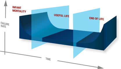
The purpose of environmental screening (burn-in, temperature cycling) is to accelerate failures due to latent defects in the “infant mortality” stage of the bathtub curve to screen weak components before they’re shipped and assembled into products. Failure analysis (FA) performed on each failing unit identifies the root cause associated with design, process, or material weakness. The goal of all these activities is to drive the dppm (defective parts per million) level to as close to zero as possible.
Once “infant mortality” cases are screened out, the remaining units in population are expected to function through their useful life and eventually fail due to end-of-life wear out. The useful “normal” life period is characterized by the lowest (albeit non-zero) rate and relatively constant failure rate (Fig. 1).
- After screening out “infant mortality” cases, remaining units in a population are expected to function through their useful life and eventually fail due to end-of-life wear out. The period of useful “normal” life is characterized by the lowest (albeit non-zero) rate coupled with relatively constant failure rate.
All parts operating in the intended application could be considered an ongoing MTBF/FIT study. Obviously, it’s not practical to let all manufactured parts operate for indefinite periods of time to observe the actual FIT rate. But, by applying accelerated stress conditions (heat, humidity, temperature cycling, vibration, load, and others) on a statistically significant sample size (usually more than 100 parts), the experiment time could be substantially shortened to expediently obtain MTBF/FIT values.
Comparing MTBF/FIT values from different suppliers for similar components without knowing actual study conditions could be misleading. Statistical by nature, MTBF/FIT values vary greatly with the number of samples used and the length of time these parts have been in operation.
To hit the target, the manufacturer must understand the customer’s minimum required MTBF value prior to designing their MTBF study. A larger study sample size and a longer operating time would produce higher a MTBF value with all other parameters being equal, including stress test conditions and number of failures. To provide an “apples to apples” comparison, the reliability report must include the number of units and hours of operation under specific test condition; these could be unified under a single term: “Total Device Hours.”
Total Device Hours is simply the number of parts used in MTBF/FIT study multiplied by their Operating Time:
Total Device Hours = Number of units in a study * Operating Time (hours)
Under different operating conditions, the MTBF value would change. But rather than performing a separate MTBF study for each stress level (such as different temperature), we can simply substitute actual Operating Time with Equivalent Operating Time, a calculation based on the well-known life acceleration factors for different stress conditions (Fig. 3).

- MTBF varies with operating conditions. Instead of performing separate MTBF studies for each stress level (i.e., different temperature), substitute actual Operating Time with Equivalent Operating Time, which is calculated based on the various well-known life acceleration factors for different stress conditions.
For example, the reliability study for TT Electronics’ OPB350 (a tube liquid sensor for medical applications including hemodialysis) used 300 units operating at 70°C for 1008 hours, resulting in 302,400 Total Device Hours (Fig. 4).

- TT’s OPB350 is used in medical applications such as a hemodialysis system.
From the results presented in Figure 5, the worst-case scenario for MTBF is 208,019 hours or 23.7 years with the device operating at 70°C with 90% confidence.

- This table reveals the stress results for TT’s OPB350 tube liquid sensor.
A claim of 90% confidence means virtual certainty, while 60% corresponds to a lower degree of certainty and higher uncertainty. Evaluation of MTBF at 90% confidence is recommended, understanding that the difference between two MTBF values at 90% and 60% confidence provides appreciation for the deployed performance time range.
For MTBF = 208,019, we can calculate FIT = 1E9/MTBF = 4,807 failures in one billion hours.
The accelerated life test performed for 1,008 hours of actual Operating Time at 70°C (158°F) corresponds to much longer Equivalent Operating Time at lower temperatures, resulting in significantly larger MTBF values at those temperatures. Using the Arrhenius relationship to determine Equivalent Operating Time at 20°C (68°F), the MTBF value with 90% confidence is 2,786,368 or 318 years (up to 797 years with 60% confidence), which is well outside the intended operating life of the device.
Create Synergy Between Design and Purchasing
MTBF/FIT studies provide a framework for determining component-level reliability, but not all component manufacturers offer this data. To rest assured that your design is based on reliable components that will perform for the long haul, it’s critical to obtain and understand an MTBF/FIT study for each part sourced. From discrete components and slotted switches to reflective sensors and Hall-effect ICs, reliability studies give you the upper hand and competitive advantage.
Knowing the optimum screening level versus cost required for your application is step one—standard COTS, military, space, or a customized version of one of these options. Step two involves determining which stress tests to conduct to eliminate infant mortality cases; be sure this is validated by accelerated testing on a statistically significant sample. And finally, by requesting reliability reports from all potential suppliers, you can readily compare values for MTBF/FIT and Total Operating Hours; keep in mind these can vary and must be supported with insight into actual study conditions.
With such valuable data in hand, design engineers and purchasing managers can be on the same page when selecting the right components for performance and longevity.
For more information contact Nijkerk Electronics.