By using an Arduino board and the MCP2515 CAN controller, you can easily control a SmartDisplay with a physical button. This code snippet demonstrates how to send commands to the MCP2515 to switch between display modes and how to read a physical button’s voltage to trigger these commands. This system can be extended to include other features, such as additional buttons, sensors, or other peripherals. The MCP2515 and the Arduino board provide a flexible and easy-to-use platform for various applications, from automotive to industrial to home automation.
In order to promote SmartDisplay products, the CAN communication could be implemented using different protocols, including CANopen and custom CAN ID protocols. CANopen is a standardized protocol that defines communication profiles, device profiles, and object models for different types of devices. It provides a standardized way to configure, monitor, and control devices on the CAN bus. On the other hand, the Custom CAN ID protocol is often used when the devices on the CAN bus have unique features or requirements that are not covered by existing standard protocols. Custom protocols can offer more flexibility and efficiency compared to standard protocols.
Guide for beginners and enthusiasts
This article serves as a guide for beginners and enthusiasts who are interested in using the Arduino board, the CAN bus shield, and sensors to control devices via the custom CAN ID. It provides an overview of the hardware components used in the project, explores the program’s functionality in detail, and discusses how to switch pages of Smart Display 7” via custom CAN ID.
Whether you are a beginner or an experienced developer, this article is a valuable resource that will help you understand the basics of using these components to control devices and the process of changing the pages via the custom CAN ID. By the end of the article, you will have a solid foundation for exploring more advanced projects with the Arduino board, the CAN bus shield, and the custom CAN ID protocol.
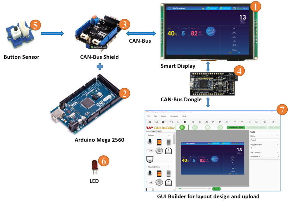
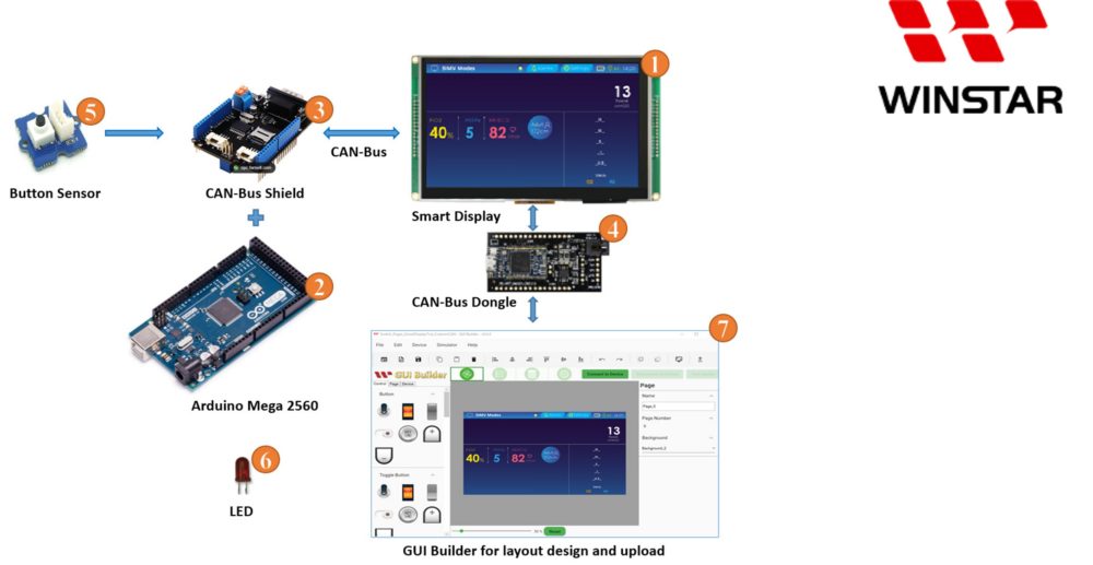
Fig. 1 System Block Diagram
The main components used in this project are the Arduino board with Arduino IDE v2.0.4, and the CAN bus shield. The CAN bus shield is an expansion board that provides a CAN bus interface for the Arduino board. The shield uses the MCP2515 CAN controller and the MCP2551 CAN transceiver to communicate with other CAN bus devices.
This demo requires the following components:
- 7″ Smart Display
- ARDUINO Mega 2560
- CAN bus shield for ARDUINO Mega 2560
- CAN bus Dongle
- Physical Button Sensor
- LED
- Software GUI-Builder v0.4.5 or above
The Demo is divided into three parts:
- Design the Demo Project in GUI Builder
- Build and Upload the Project\
- Program the Arduino Host
Design the Demo Project in GUI Builder
To begin, launch an up-to-date GUI builder and create a new project. Assign a name to the project, and the project folder will be automatically selected.
Choose the device type, in this case, device type 7″, and select the protocol « custom CAN ID ». By default, the display orientation will be in landscape mode. Choose a blank UI template, and click on the create button to generate your new project, as demonstrated in Figure 2.
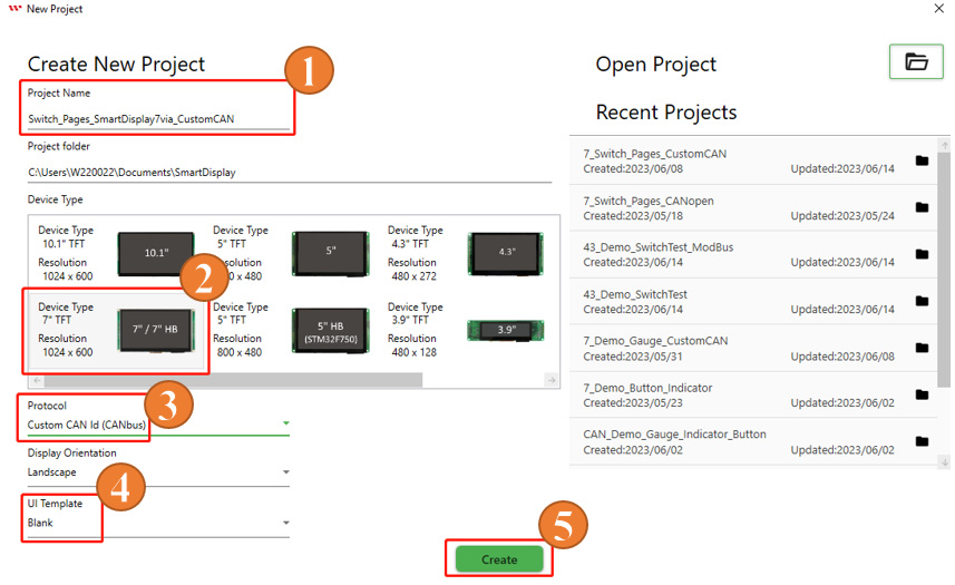
Fig. 2
This page opens after creating the blank project.
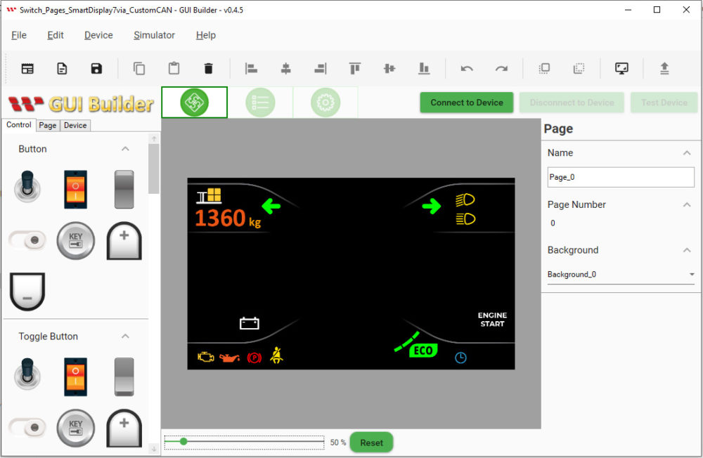
Fig. 3
As per the demonstration scenario, an additional page is required. To add this page, click on the page button and then select the plus button.
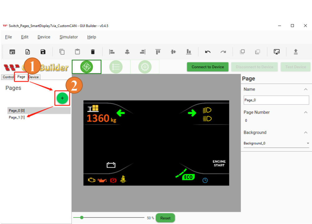
Fig. 4
It is possible to choose the customized background style from the resource panel.
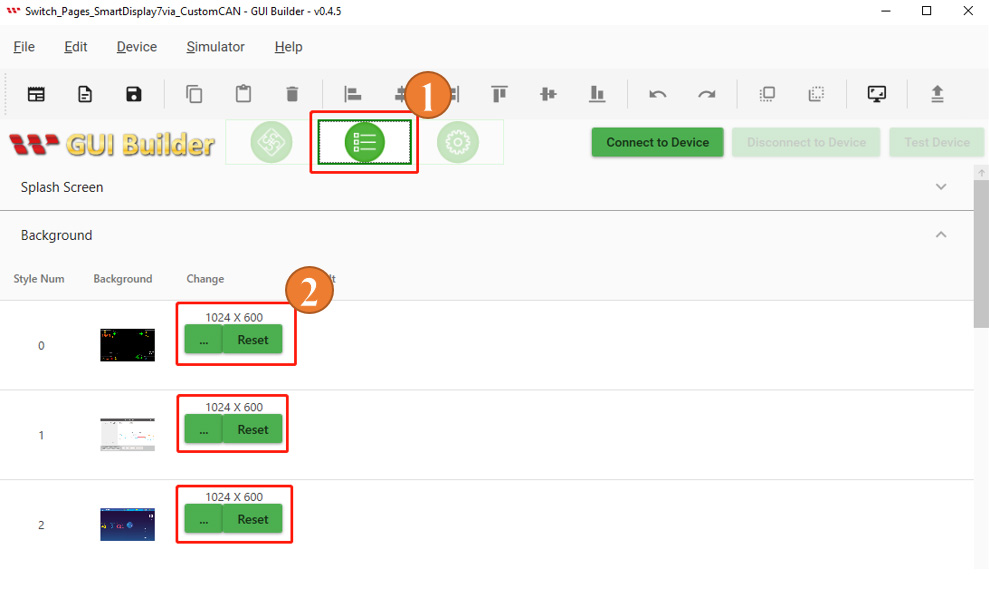
Fig. 5
You can also choose your preferred background style in the page section.
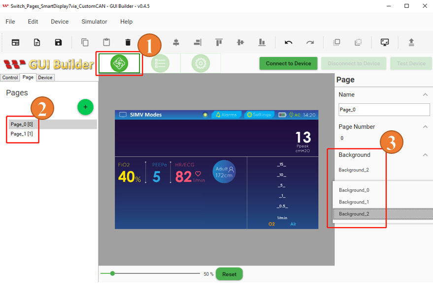
Fig. 6
Build and Upload the Project
After finalizing the layout design and completing the previous steps, the next step is to build the project. Click on the Device button and select Device Property. Review the default protocol and baud rate settings based on your needs. It is recommended to set the baud rate to the same value in both your Arduino code and the GUI builder to ensure compatibility. Once you have made any necessary changes, click on the Connect to Device button. If the device connects successfully, click on the upload button to upload the project, as shown in Figure 7 below:
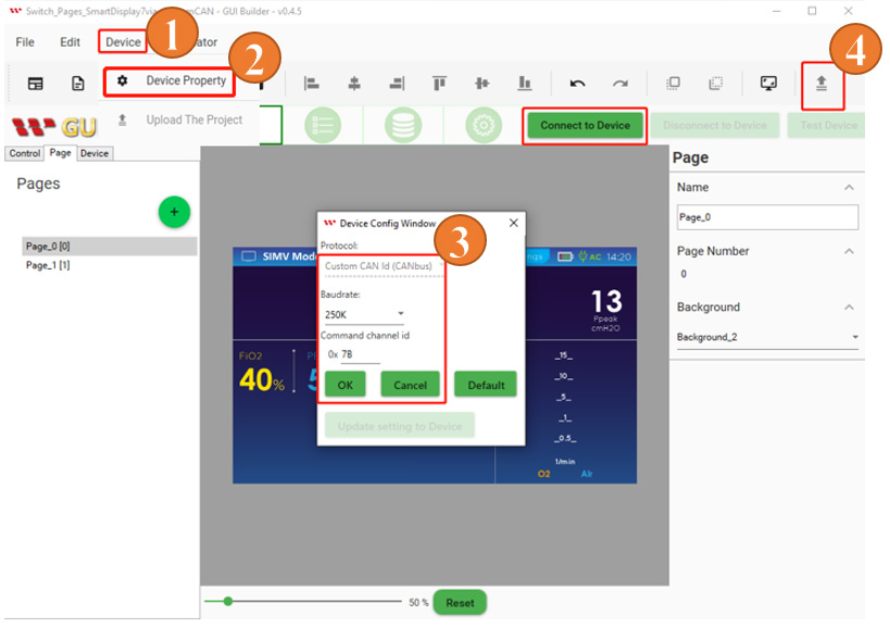
Fig. 7
When the Upload project is completed then click on the ok button as shown below Fig 8:
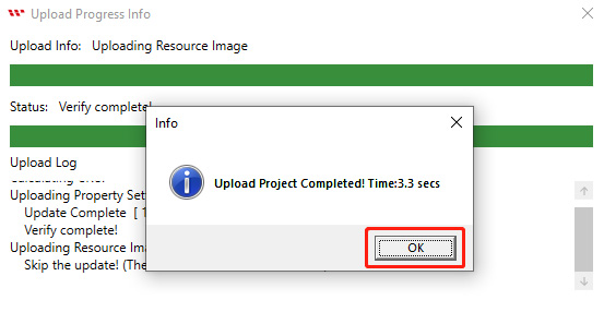
Fig. 8
The start screen will appear after uploading is completed as shown below Fig 9:
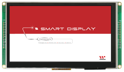
Fig. 9
After the start screen, it will jump to the uploaded design page. Now Building and uploading has completed through GUI builder as shown below Fig 10:
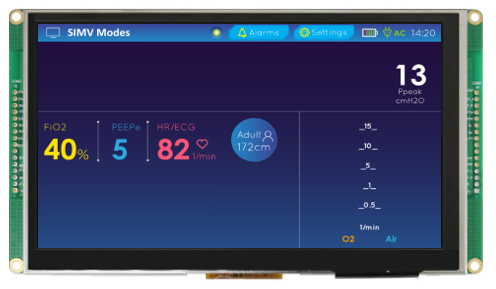
Fig. 10
Program the Arduino Host
There are only one “mcp2515_can.h” library has been used for the Custom CAN ID protocols. And another “SPI.h” library is used only for Serial Peripheral Interface (SPI) communication. The mcp2515_can.h library is used for interfacing with the MCP2515 CAN (Controller Area Network) controller, which is a widely-used CAN controller for embedded systems.
The library provides functions for initializing the MCP2515, setting up the CAN communication settings (e.g. bit rate, filter, and mask settings), transmitting and receiving CAN messages, and checking for errors. Here all required register addresses are defined in the Arduino IDE program as shown below in Fig 11. This code segment initializes various global variables, constants, and arrays with their respective data types that are used later in the code.
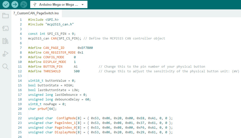
Fig. 11
This code segment is the setup() function that is called once at the start of the program. The serial communication for serial monitor is initialized with a baud rate of 115200 using Serial.begin(). The built-in LED on pin 13 is set as an output using pinMode(). The physical button pin is set as input using pinMode(). A while loop is used to initialize the MCP2515 CAN controller. The CAN.begin() function is called with a baud rate argument of CAN_250KBPS.
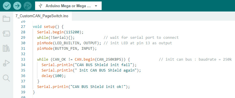
Fig. 12
Here the changePageFunction() function sends commands to the MCP2515 to switch between display modes. It does this by sending messages with specific data bytes to the MCP2515. The function first sends a « device mode » command to switch the MCP2515 to config mode, then sends a « change page » command with the desired page number, and finally sends another « device mode » command to switch the MCP2515 back to display mode.
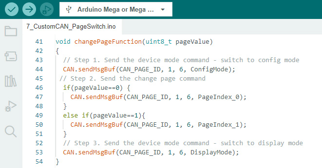
Fig. 13
This code segment is the loop() function that runs repeatedly after the setup() function is called. The function reads the voltage value of the physical button using analogRead() and stores it in the buttonValue variable. If the buttonValue is greater than the THRESHOLD value, it means that the physical button is pressed. In this case, the function increments the nowPage variable by 1 and prints the current nowPage value to the serial monitor using sprintf() and Serial.println().
The function then calls the changePageFunction() with the current nowPage value to switch to the desired display page. If the nowPage value is not 0, the built-in LED on pin 13 is turned on using digitalWrite(). Otherwise, the LED is turned off.
The lastDebounce variable is updated with the current time using millis() to keep track of the last button press time. The function waits for the physical button to be released by continuously reading the buttonValue using analogRead() inside a while loop.
And last but not least, the delay(100) statement at the end of the function introduces a 100 ms delay before the function runs again. This delay ensures that the CAN bus messages are sent at a reasonable interval.
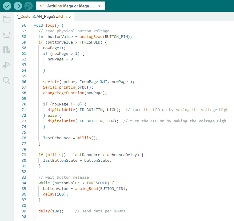
Fig. 14
For more details, see the Arduino code. It is important to take note of the address to connect the host with Smart Display. If you want to learn more about how communication between the host and smart display is via CAN bus Shield, please reference the GUI builder communication log.
Appendix:Set Up the Project
Once you have successfully verified and uploaded the program through the Arduino IDE, it should be possible to switch between pages by pressing physical buttons. When the screen displays the first page, the LED will turn off. Pressing the physical button to switch to the second page will cause the LED to turn on, as illustrated in the below Fig 15:
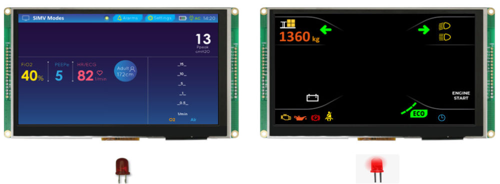
Fig. 15
Congratulations, the design and demo of the Smart Display is completed with a physical button and LED to change the Inductor color while pressing the physical button or touch button.
Please refer to this link of GitHub https://bit.ly/3oT0o5M to download the above program, demo video, and can seek more details about other demo project in example. The actual hardware setup is given below fig 16 :
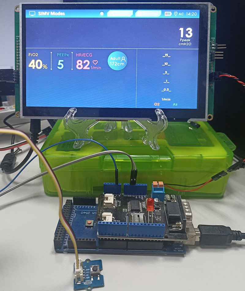
Fig. 16
If you want more information or if you have any questions, please contact Nijkerk Electronics!